The structural analysis software RFEM 6 is the basis of a modular software system. The main program RFEM 6 is used to define structures, materials, and loads of planar and spatial structural systems consisting of plates, walls, shells, and members. The program also allows you to create combined structures as well as to model solid and contact elements.
RSTAB 9 is a powerful analysis and design software for 3D beam, frame, or truss structure calculations, reflecting the current state of the art and helping structural engineers meet requirements in modern civil engineering.
Do you often spend too long calculating cross-sections? Dlubal Software and the RSECTION stand-alone program facilitate your work by determining section properties of various cross-sections and performing a subsequent stress analysis.
Do you always know where the wind is blowing from? From the direction of innovation, of course! With RWIND 2, you have a program at your side that uses a digital wind tunnel for the numerical simulation of wind flows. The program simulates these flows around any building geometry and determines the wind loads on the surfaces.
Are you looking for an overview of snow load zones, wind zones, and seismic zones? Then you are in the right place. Use the Geo-Zone Tool to determine quickly and efficiently snow loads, wind speeds, and seismic data according to ASCE 7‑16 and other international standards.
Would you like to try out the capabilities of the Dlubal Software programs? You have the opportunity to do so! The free 90-day full version allows you to thoroughly test all our programs.
The differences between both RF‑/DYNAM Pro add-on modules Forced Vibrations and Equivalent Loads are explained in FAQ 002062.
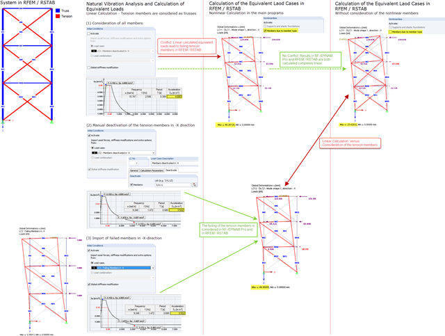
When the settings are the same, the same results should also be calculated in both add-on modules. However, this does not apply to existing nonlinearities, as no nonlinearities are considered in the RF‑/DYNAM Pro add-on module. When displaying the results in the Forced Vibrations add-on module, all nonlinearities are thus ignored. In contrast, the equivalent loads are calculated on a linear structural system, but the exported load cases are then calculated on a real structure in RFEM 5 and RSTAB 8 – that is, with all nonlinearities. This may lead to inconsistent results. If you deactivate the nonlinearities for the exported load cases, you should obtain the same results.
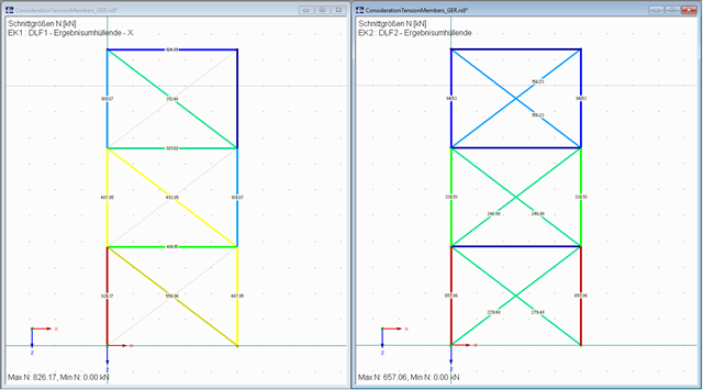
The method of considering nonlinearities in the response spectrum analysis is described on the basis of tension members in FAQ 002237.
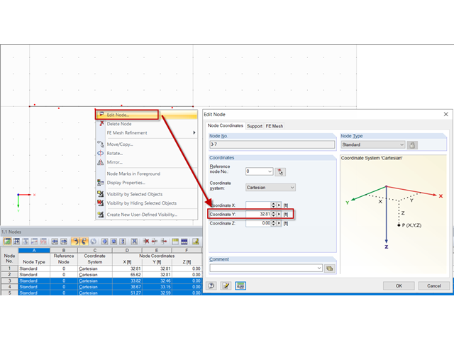
The fastest way is to edit the coordinates of several nodes at the same time. To do this, proceed as follows: Select all affected nodes (by drawing a window or by selecting them using the Ctrl key) and edit them (for example, by double-clicking one of the selected nodes). The "Edit Node" dialog box opens. The coordinates that are already uniform are specified as a value. No value is displayed in directions where the values differ. You can adjust the coordinates for all nodes at the same time.
In the example shown, you should enter the Y‑coordinate to the desired value in order to move the nodes on the line. The procedure is shown in the attached video.
If you want to divide the line by the nodes afterwards, you can use the "Connect Lines or Members" function. Thus, the line is divided into nodes and several new lines are created.
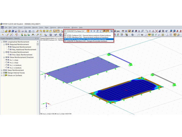
The results of most add-on modules can be displayed easily in the graphic of the main program. There are two options for this:
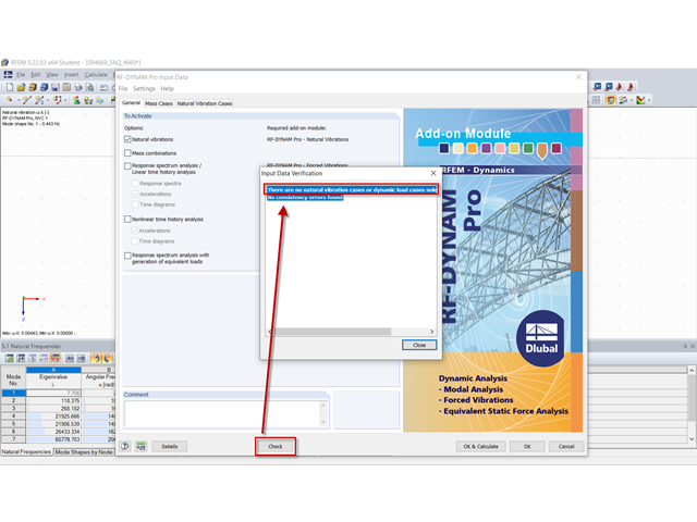
This message appears if all defined natural vibration cases or dynamic load cases have already been calculated. The reason is that the check only goes through the input data that have not yet been calculated.
Thus it can be said that the check should only be applied before the calculation. If there are any input errors, the calculation cannot be performed anyway.
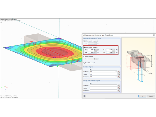
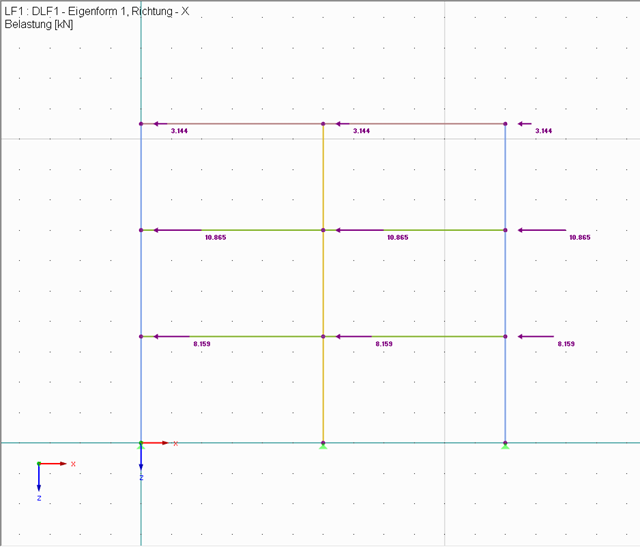
The RF‑/DYNAM Pro - Equivalent Loads add-on module allows you to perform a multimodal response spectrum analysis. Equivalent loads are created and exported in load cases to the main program RFEM 5 or RSTAB 8. The load cases are created separately for each selected mode shape and excitation direction. You can display the loads as usual.
The equivalent loads are generated at each finite element node (or each inner node). If the number of generated loads is too large, the graphical display is deactivated. You can change this setting in the details of the RF‑/DYNAM Pro add-on module.
Dynamic analyses, such as the determination of natural vibrations or the response spectrum analysis, are always performed on linear systems. To consider nonlinearities such as tension members in a dynamic analysis, a complex procedure is necessary. This procedure is described for the add-on modules Natural Vibrations and Equivalent Loads in this technical article.
However, you should consider whether this complex consideration is necessary for your system or whether the linearization is sufficient.
In the Nonlinear Time History add-on module, tension members are considered as usual. An example is described in this technical article.
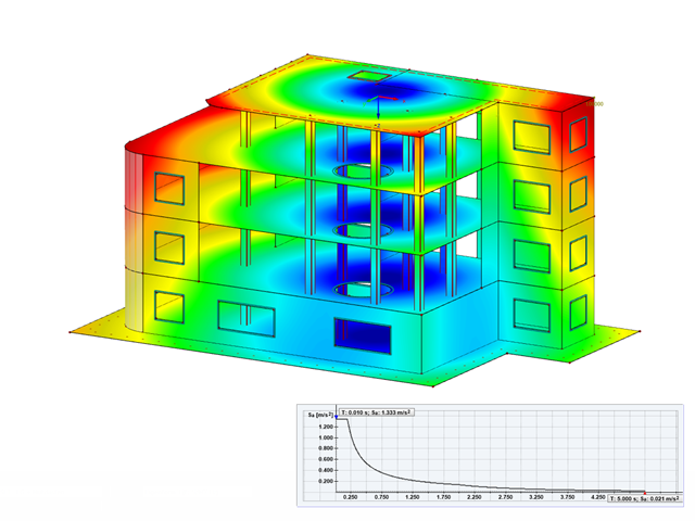
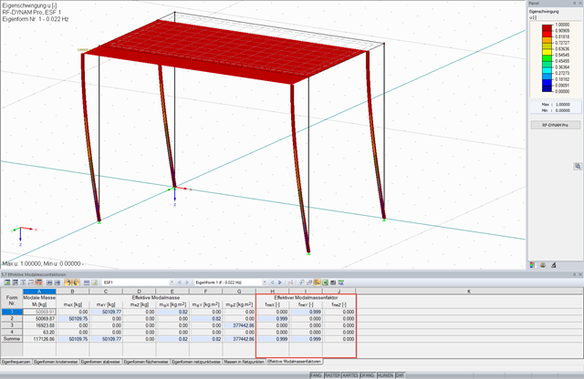
According to EN 1998‑1, enough modal forms should be used that the sum of the effective modal masses is at least 90% of the effective total mass (usually this corresponds to the total mass of the structure). This regulation can be different in other seismic standards.
The input window of RF‑/DYNAM Pro contains the "Mode Shapes" tab under Dynamic Load Cases, where the frequencies and effective modal mass factors are summarized in a table. This allows you to check before the calculation whether it is necessary to determine the required number of eigenvalues or to increase the number.
After the calculation, the effective modal masses and the factors are displayed in Table 5.7 Effective Modal Mass Factors.
This FAQ lists the causes of small effective modal mass factors and the possible solutions.
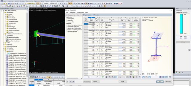
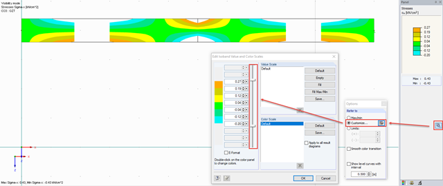
Yes, you can define an area in the panel by clicking the "Options" button. Here you can define a customized area by moving the slider. In that case, the areas with higher or lower stresses have no color.
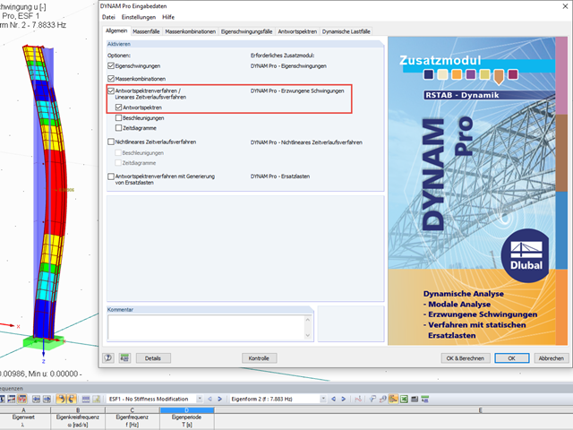
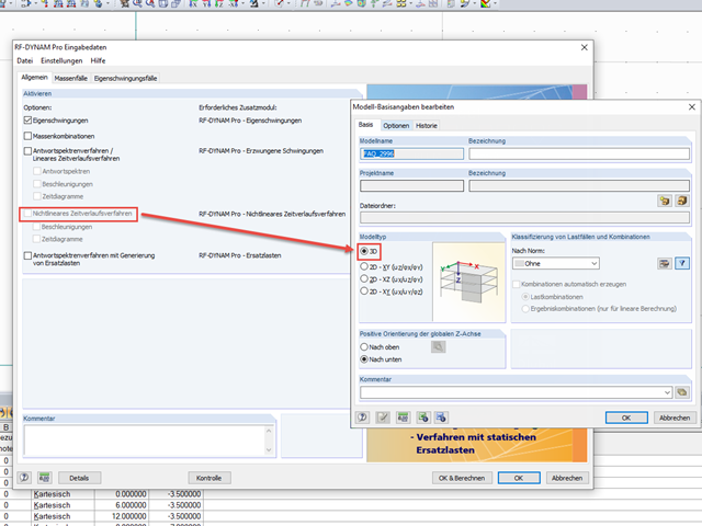
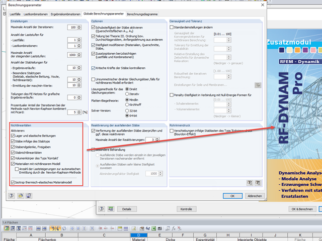
In the program parts Natural Vibrations, Forced Vibrations, and Equivalent Loads of the RF-DYNAM Pro add-on module, a linear calculation is performed. Nonlinearities, such as failure under tension or nonlinear material properties, are ignored. For example, cables or tension members are replaced by the Truss member type. This results from the calculation methods: Both the natural vibration analysis and the response spectrum analysis are purely linear methods.
The "Nonlinear Time History Analysis" program part provides a nonlinear time history analysis of time diagrams (any excitation of the structure) and accelerograms (excitation of supports) using an implicit and explicit analysis. In this case, many nonlinearities that can be defined in RFEM 5 or RSTAB 8 are taken into account.
In RFEM, it is possible to determine a pushover curve or a capacity curve and export it to Excel. In the following, you can find a list of the steps that must be performed:
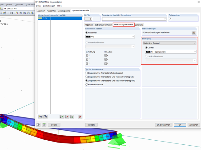
A load distribution similar to the mode shape distribution can be generated automatically with the RF‑DYNAM Pro - Equivalent Loads add-on module. This module determines eigenvalues and equivalent loads based on the response spectrum analysis. For each selected eigenvalue, equivalent loads are generated and exported to RFEM in load cases.
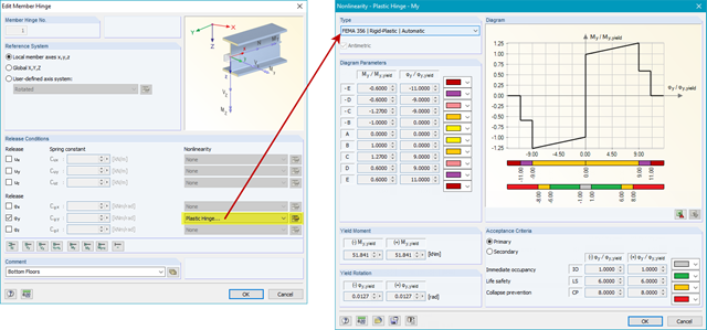
The color display of the plastic hinges is shown in Image 05. You can select the color scale according to the acceptance criteria or according to the defined parameters of the hinge diagram.
A further pushover analysis (determination of the inelastic spectrum, performance point) can then be performed, for example, in Excel.
In the download section below, you can find a detailed description of this tutorial within a PDF document (in English).